Chapter 1: getting the CAD and printing the parts.
These are the designs and plans for a fully functioning 2in ultra low profile 3D printed Crayford focuser which anyone, with some basic tools and a 3D printer, should be able to easily make. I have designated this to be open source so anyone can make/modify/redesign/adjust to suit.
It’s key features are as follows:
- Ultra low profile of 38mm racked in. Basically the lowest thing out there after Don Clement’s “Clement focuser”.
- 30mm of travel.
- Circa 300g depending on print infill density/material
- All main parts 3D printable. Including the pinion pusher block
- Off the shelf bearings and screws bolts etc..
- Only parts self fabricated are the bearing runners in 1mm sheet aluminium which is very easy to cut and the 5mm stainless steel rod cut to 105mm length.
- Can take loads of up to 1.5kg with a brake or currently 0.75kg without a brake. Note this version Mk1 does not yet include a brake.


So first of all the files (this is the tricky bit).
Method 1:
I have uploaded the entire model INCLUDING the screws, inserts and all hardware fixings to GrabCAD. Also included is a BOM (bill of materials listing Everything including fixings and hardware). The files are in the native Solidworks 2017 format so they can be edited and saved as STL’s. This is primarily for people who have access to the CAD and would like to modify. GrabCAD is primarily aimed at the engineer.
https://grabcad.com/library/2in-crayford-focuser-mk1-1
Method 2:
I have uploaded all and only the parts for 3D printing as STL’s to Thingiverse. This is primarily aimed at people with no CAD facility to simply get the models and begin printing. You can download these and print straight off for assembly. Also included is a BOM (bill of materials listing Everything including fixings and hardware). On top of this you must also cut the bearing strips out of 1mm plate aluminium. The roller bearing strip is 60mmx10mm; you will need 2 of these. The pinion bearing strip is 60mmx10mm; you will need to make 1 of these. The pinion its self you will need to buy 5mm OD stainless steel bar and cut to length; 105mm.
https://www.thingiverse.com/thing:4424419
So you’ve downloaded the files, opened your slicer now what setting to use….the million dollar question!!!

Behind every great print in a great bunch of settings and this is really tricky as there’s no way I can make your prints great. This piece of precision mechanics is designed in such a way that i’ve tried to design out all of the tolerances so that when you print it, regardless of your printer capabilities or the tolerances it holds it should still work well.
Recommended settings:
What i’d use are the following setting for PLA. (I use matte black enhanced PLA from Filaprint in the UK. If you are an advanced user you would be better off using CF PETG or ABS.
- Speeds in the order of 40-45mm/s for the larger parts. 10-15 for some of the smallest parts like the pusher pins. Remember you’re wanting this print super neat. Faster = less accuracy.
- PLA temps at the LOW end of the recommended material temp because you want to limit excess oozing or over-extrusion.
- Medium fan settings of 20-50% as you want strong prints.
- main drawtube fill 50%, 1.6mm-1.8mm wall
main base plate fill 20%, 1.6mm-1.8mm wall
all other parts 100% fill - No raft, no support ANYWHERE! (angles are build in on overhangs to allow the print layer to build up slowly without bridging at 90deg. Classic example is the Focuser know printed smaller diameter part face down on bed.
- Highly recommended to print on Glass with 3D lac.
- Layer height 0.2mm. if you know what your doing with adaptive layer heights then go for it with for example the focuser knob to get neat prints.
- If you can, print item “CRAY_Pusher block” in Nylon for a smoother ride. Nylon is a great bearing material. If not PLA will work anyway.
Total print time is in the order of 24hrs for all the parts. If you’ve got your retraction settings dialled in nicely throw them all on the bed at the same let and set going. Otherwise print individually. this is because you can get stringing between the prints on a badly set up printer.
Chapter 2: The BOM, sourcing and making the non printed parts.
So here is the BOM (that’s engineer speak for all the parts) in all it’s glory. There’s not a whole lot to it, as evidenced by the fact that the assembly is only taking about an hour.
Orange items are standard off the shelf parts.
Blue is material purchased and fabricated by you. More detail in the fold!!
Green are your 3D prints.
SIMPLES!!!!

So you’ve printed the green parts out (please don’t use green filament!!!) and wondering what happens next. I would advise by this time you would have already ordered some flat 1mm aluminium sheet and some 5mm steel rod for your pinion (preferably stainless).
So to make your pinion and bearing runners first cut the aluminium strips out. The bearings ride on the strips 60mm x 10mm and you will need two of these. I simply scored deeply with a Stanley knife whilst wearing some tough gloves. [That’s not a liability disclaimer by the way as I’ve genuinely sliced the end of my thumb off cutting aluminium like this.] Be warned. Or more sensibly slip them over your band saw. Make the 60x20mm strip for the pinion runner the same way. Deburr the edges and gently wet and dry the surfaces off all of the strips with a 400-800 grade. This does 2 things; it keys the surface for bonding and flattens the parts so they make a good bearing surface. Secondly cut the 5mm diameter rod to length – 105mm- and grind off the sharp edges. This fabrication is by far the most onerous; the rest is a BREEZE!!!!!!!
NOTE: some would advocate the use of stainless steel sheet as the bearing runner surface. A good idea, but more difficult to work with and keep flat after cutting, unless it’s laser cut. But that defeats the purpose of a $10/£10 focuser doesn’t it?!!
Order the bolts, inserts and bearings. here are some UK suppliers:
Screws, grub screws.
Bearings. (for this particular CAD design they must be 3x8x3mm)
Inserts.
Note for the M4 x 25 Socket Cap screw you will want to use a Nylon screw as this is for the lock knob and you really don’t want to be locking in your 2in eyepiece or coma corrector with a steel screw! in MK2 i’ll likely replace this with a brass ring but for now a Nylon screw is readily available and works well.
You’re ready to go with build launch!!!!!
One thing I would add is decide now if you wish to glue or stick with double sided tape the bearing runners to the drawtube. Try keep with a thin layer of say 0.25mm VHB if the latter. If bonding, get some 2 part epoxy. Either will last a lifetime.

Chapter 3: Assembling the focuser.
Before we begin assembling the focuser i’m going to show you a little trick that will change your life. You’ll never view fixings for plastic again the same way and you’ll wonder why you’ve never done this before. This is what all the 3D printing gurus do to their plastics for super strong fixings instead of trying to tap for a thread!!!
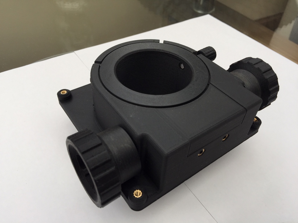
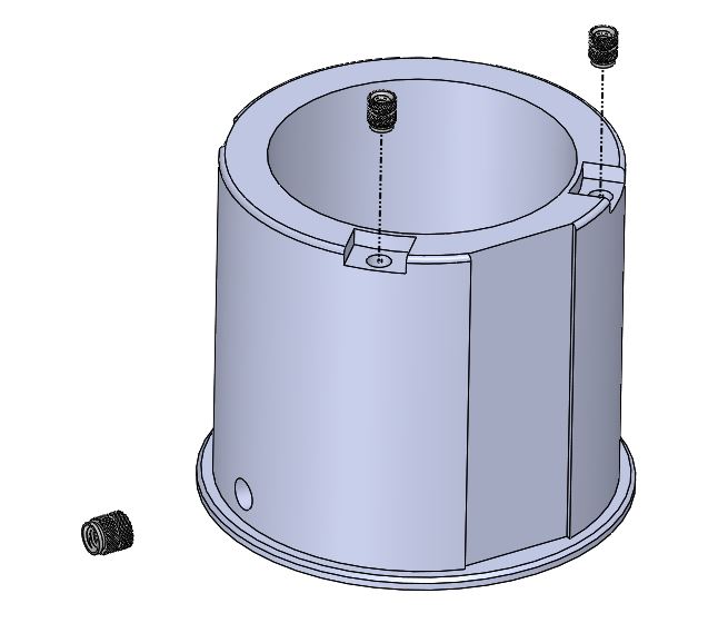
It doesn’t need many words. You simple melt the inserts into the 3D print with a soldering iron. For even stronger fixing than in the picture melt a flanged insert from the other side where applicable (for example where I melt the M4 inserts in for the pinion push block bolts)

So you want to get all the inserts melted in in one sitting. First up is the base plate. 8 M3 inserts get melted into the bearing runner holes and the mounting holes. The 2x M4 flanged inserts are melted in from the INSIDE, VERY IMPORTANT!!!

Next the tension cover plate gets 3 x M4 inserts melted in. Melt these inserts right in below the surface.

……….followed by 2x M3 inserts in the bottom of the drawtube and 1 x M4 insert in the side of the drawtube. Note these inserts need to be flush or just below the surface.
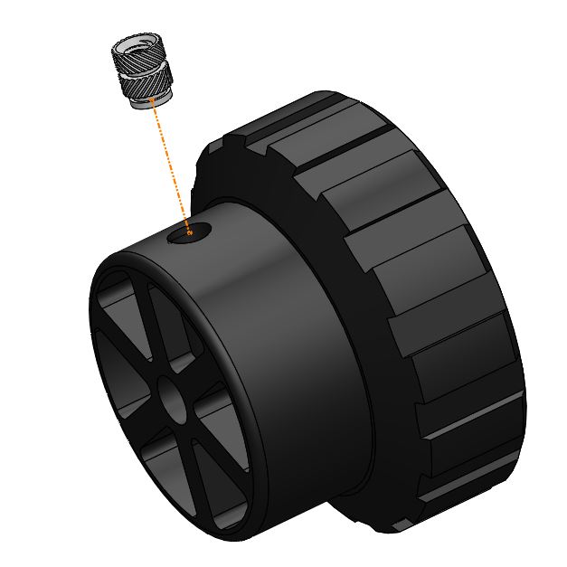
Then the 2x M3 inserts (one in each turny knob thing)

And lastly the thumb lock knob for the drawtube, 1x M4 insert.

Bonjour, belle réalisation merci pour le partage
LikeLike
A friend has printed this for me but I only have one 2″ eyepiece. Do you have a design for a 2″ to 1.25″ converter?
LikeLike
Beautiful design, do you have a *.step file you can post? I don’t have solidworks but I would like to modify the base for a refractor.
LikeLike
Hi David, good to hear from you. Can you give me till next week say Monday-Wed. I’m super busy this weekend.
LikeLike
No problem, thanks! David
LikeLike
Can you PM me your email address so Ican export the STEp to you?
LikeLike
Hello. I’m trying to use this as an add autofocuser for my refractors. Did you manage to modify the model? If yes, any chance you can share? eavaria (at) gmaiI
LikeLike
HI yes, full STEP filesets that i’ve sent out beforeto people. If you PM me your email address i’ll send you all the files. Kind regards, Marco.
LikeLike
Is this dual speed? Btw I really appreciate your effort on this. For someone who lives in a high inflation country (like me) that can’t easily purchase astronomy parts like this. This project is a lifesaver.
LikeLike
Hi, no single speed. But as this is only V1 who knows!!! No engineer ever stopped at V1.
LikeLike
Great work. Is it possibile to have the STEP files?
LikeLike
Hey, sorry for the late replty, yes absolutely no problem. I’ve already compiled the STEP’s for someone else so I can sent the pack to you.
LikeLike
Is it possible to get the step files? I would like to alter the baseplate to fit my 7″ telescope.
LikeLike
Hi Marco, great work! Thanks for sharing. May you kindly make available the STEP files for your 3D model? I use FreeCAD.
Best regards
Gigi
LikeLike
Hi Marco, Russ here in Canada. I don’t know anyone who could 3d print. Would you be interested in building a 2 inch low profile crayford focuser. Price?
Thanks
LikeLike
Hi Russ let me get back to you and time is a problem for me right now……how quickly are you needing it? Does it require any customisation for example this base plate fits a flat OTA, but many people have round OTA’s…
LikeLike
Hi , I don’t need it until January and it would be mounted on a flat board
LikeLike
I built this and made some mods for my own purposes, it’s working very well! Original STEP files at : https://drive.google.com/file/d/1bkT5misULNnbhHTuaJwszPdleyy7HbcQ/view?usp=sharing
LikeLike
Superb, glad you like it.
LikeLike
What a great product.!!
Just one question, though. Do you have any more details on the springs?
I.E Diameter, length ,strength etc, etc
LikeLike
Hi Neil, details to follow. The fixings are more detailed over at GRABCAD and this includes CAD of the actual spring.
LikeLike