Setting up a Foucault test for the 7.5in Mirror.
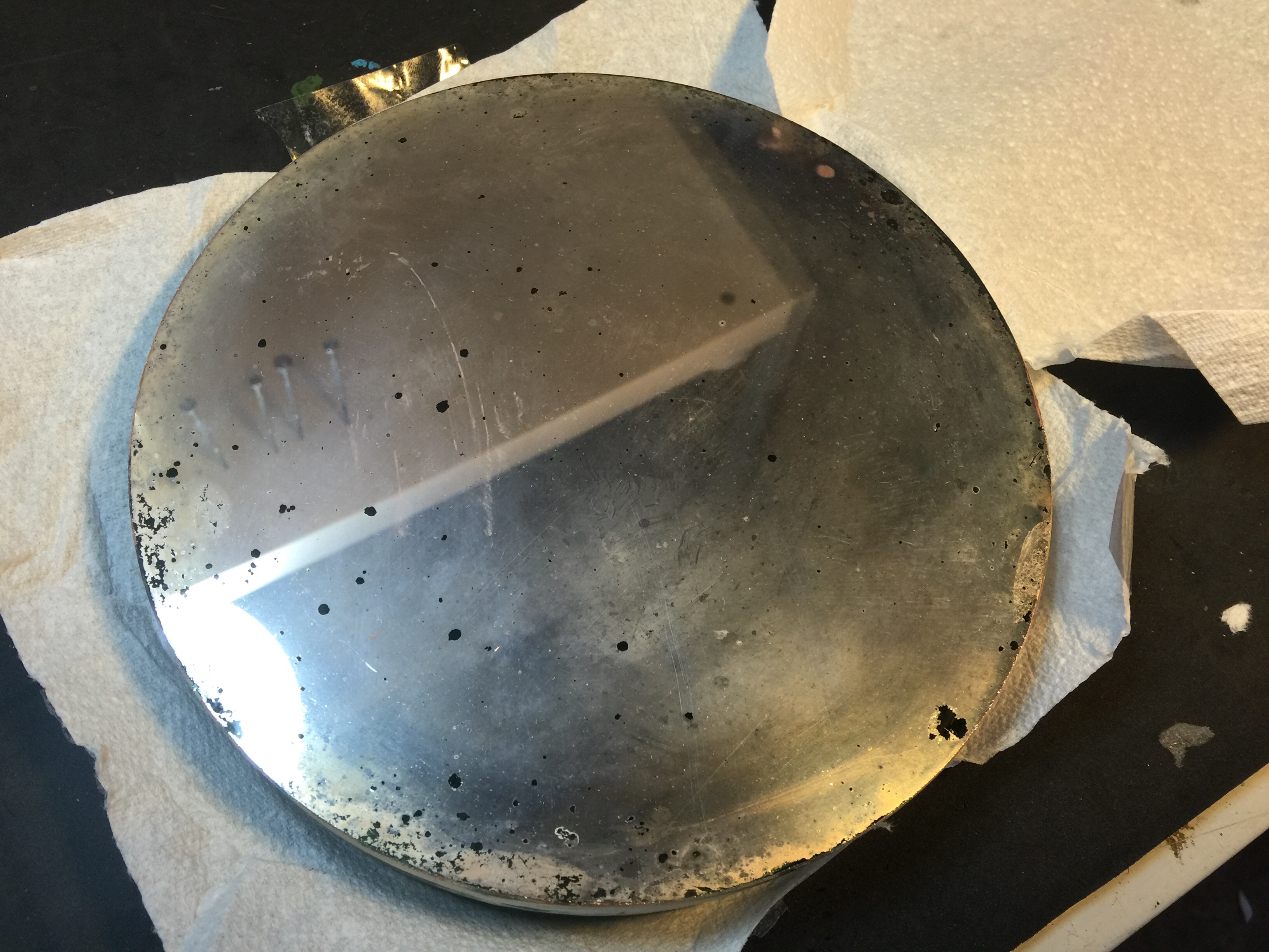
Having never done any direct mirror testing before and having been told the antique scopes’ mirror was ‘slightly’ over-corrected by half a wave I thought some investigation would be in order.
A bit of background on mirror testing first. Any Newtonian telescope mirror must bring it’s rays to a focus within a certain tolerance that we measure indirectly as ‘Wavefront error’. The Raleigh criterion is 1/4 wave peak to valley of the WORST part of the wavefront, or better still the Danjon-Couder criteria of 1/14th wave RMS. We are talking about surface irregularities or MILLIONTHS of an inch!!! Mel Bartels has an excellent explanation here: http://www.bbastrodesigns.com/ratemirrors.html .
We are going to measure, to millionths of an inch, any surface irregularity with and LED, a razor blade, a table that moves on 2 axis, a test stand for the mirror and some Lego.
The test stand made was adjustable so it can take any size of mirror (apart from my 20in mirror that I’m too scared to remove from it’s box and actually put in a telescope):


It’s basically a lot of thick plywood cadged together with slots cut for the blocks that support the mirror at the front. Concentric circles were drawn on it so the OA (Optical Axis) was easier to line up each time a different mirror was put on.
There is a huge wealth of information on the web on building and using a Foucault tester but by far the best resource has been the book “Understanding Foucault” by David. A. Harbour, available on Amazon Kindle for a few great British pounds. I mean the currency not the weight. This book is worth it’s weight in gold. I mean the weight, not the currency. Stellafane also have great info on Foucault testing.
There are as many ways to build a tester as there are recipes for pasta so I designed one with my son made from Lego! A real live working Foucault tester complete with movement in both axes.
 I know what you are thinking, and my wife thinks so too, but you are wrong.
Anyway what you are staring at is the ‘business end’ of the Foucault tester. You look past the knife edge at the mirror located on the radius of curvature (in the case of the mirror I am testing, 136 inches away). What you are looking for is the returned image of an LED that will be placed BEHIND the knife edge that will effectively amplify any deviation from a sphere in the surface of a mirror right down to, as I said before, millionths of an inch. Incredible eh?
I will put up a section with more detail on the design of this tester on my main pages……
So that’s the test setup. I’ll get back to being in the garage till 2AM on the night of the 12th March 2016. The night was eerily quiet. Nothing could be heard except for the sounds of mice scampering around the logpile. An owl hooted. Little beknownst to me, bedtime was a long long long while away yet; in a galaxy far far away…….freezing in my garage was the least of my frustrations. An important point to note: the temperature must be fully stabilized before testing commences otherwise silly readings will be gotten. You have been warned.
I created a Zonal mask in CAD and printed it out as a DXF file as seen hanging from the front of the mirror. The zones can be calculated using a nifty little web calculator such as this. There are plenty online. It basically splits the mirror up into segments of equal area.
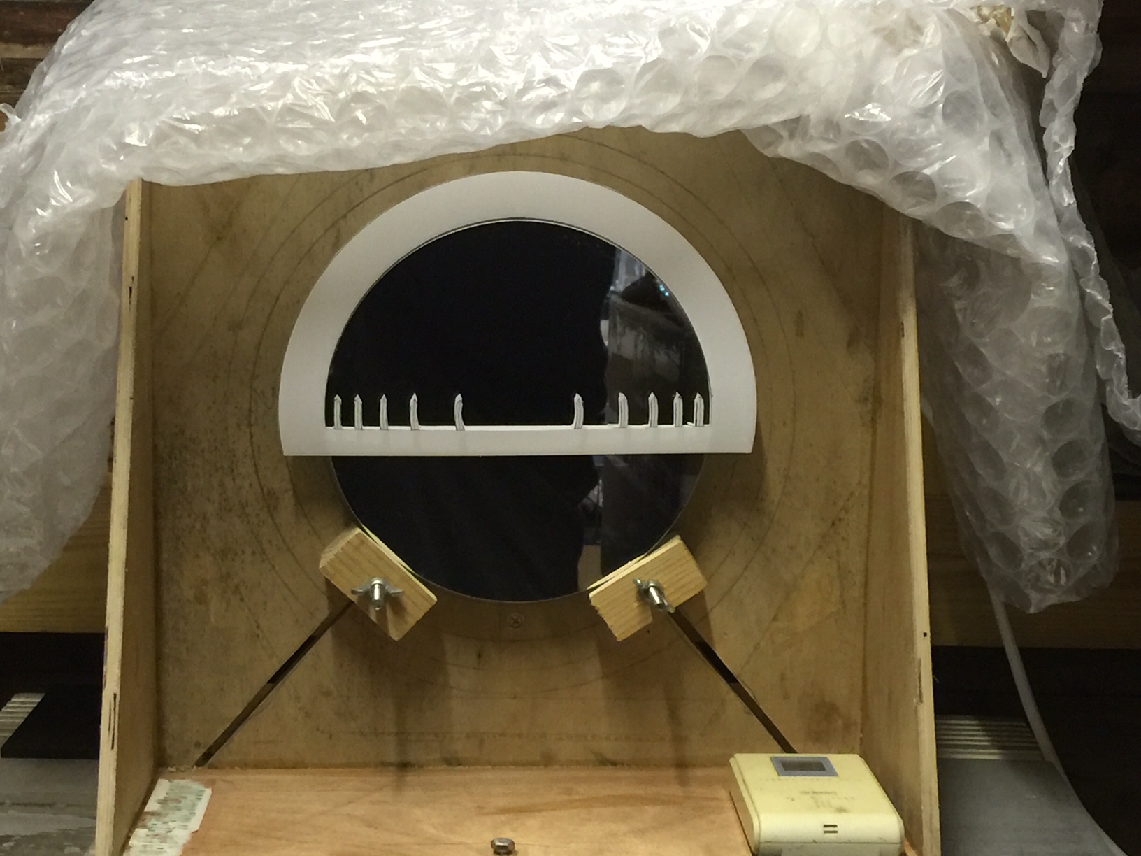
There’s a thermometer in there to log the temperatures so I know it’s stable first.
The blocks holding the mirror up are tapered slightly backwards so the mirror rests safely on the backboard.
The Zonal mask is placed carefully over the front. I didn’t get a chance to set up a camera but the Foucault image with the test apparatus all set up correctly and the LED switched on and the lights all turned off and the garage being all spooky, you see something very similar to this:

This is an image at the 0.707r zone being nulled which, in a 5 zone tester like i’ve done, is the 3rd marker in.
Whats happening with the Foucault test as you are taking measurements is you start off at the radius of curvature or point at which the intersecting rays from the mirror are at their narrowest. You then take measurements on the y-axis (for example with a dial gauge) at each of the zone markers. You are ‘nulling’ each zone and in doing so chasing the doughnut from the center of the mirror out to the edge.
Once you have a set of measurement you can compare them to the ideal mirror and literally build up a picture of how close your mirror is to the ideal.
Here is my Lego tester head. On the bottom right there’s a dial gauge, 0.01mm, 0-25mm and that is what you take measurements with. It’s axis is parallel to the optical axis. You are moving the test bed that has the knife edge and LED along the y axis whilst nulling these zones whilst staring directly past the knife edge. It’s all such fun in a cold dark damp garage with sore eyes, cold fingers and trying to not bang into the test head with your frozen eyelashes and catch the tiniest little glimpse of a doughnut whilst craning your neck and head behind the back of the tester head window.

It does get easier the more you do it and there is a steep learning curve with finding the image; it can be very tricky to begin with. Also the LED brightness has to be carefully tuned with a specific resistor. With Foucault, the dimmer the better. So eventually i managed to get 3 sets of actually quite sensible readings.

I won’t bore you with the mathematics of the formula driving this sheet as it’s amply covered in many sources but essentially what you are looking at is the shape of the mirror. The red/blue dashed lines represent the outer limits of where I can be. The green dashed line is the ‘perfect’ mirror. The solid lines are my measurements, the light green being the average of 3 readings on each zone and the black being the same line shifted down to ‘best fit’ the limits. This is normal and permissible as it just means you started out too far up the y axis and need to shift the whole line up/down i.e. the shape remains the same.
So where does all this leave me in the end? Well with a very rudimentary test setup and a lot of patience I was able to get fairly consistent and sensible results that are a/ self checking and b/ agree in principal with what Orion Optics told me about this mirror; that it is slightly overcorrected. [incidentally not by as much as the 1/2 wave they said it was!!!] That is, the mirror is a bit more parabolic than it should be, likely because in 80+ years the glass has slumped.
The best fit line, solid black, indicates that it is boderline on being within my permissible zones i.e. almost accurate to 1/4 wave so all the rays should come to a *reasonable focus. However is does not satisfy the 1/14th wave RMS and some basic calcs. show that to be around 1/9th wave RMS. ie all zones considered there’s just too much deviation across the entire wave front to be acceptable.
However the story just begins here because as I said before I don’t intend to stop until I get the mirror to that green dashed line or at least very close to it…………how I do that…..well that’s a secret yet to be revealed. (I have actually given a clue in a previous post). I guess next time I get it re coated I could get it re-parabolized and pull in that outer zone but for now ‘I have a cunning plan’. TBC.