Designing a High Quality 3D Printed Crayford Focuser

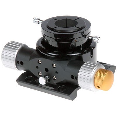
The Brief is simple but challenging. Design a Crayford focuser that is 3D printed, Ultra-low profile, performs as well as any $$$ commercial Crayford focuser, even lower profile than can be purchased, LOOKS GOOD, requires NO post machining, can lift 1kg of equipment at full extension and can be assembled with off the shelf bearings and fixings. That’s reasonable surely?!!

A Generic Commercial Low profile Crayford focuser

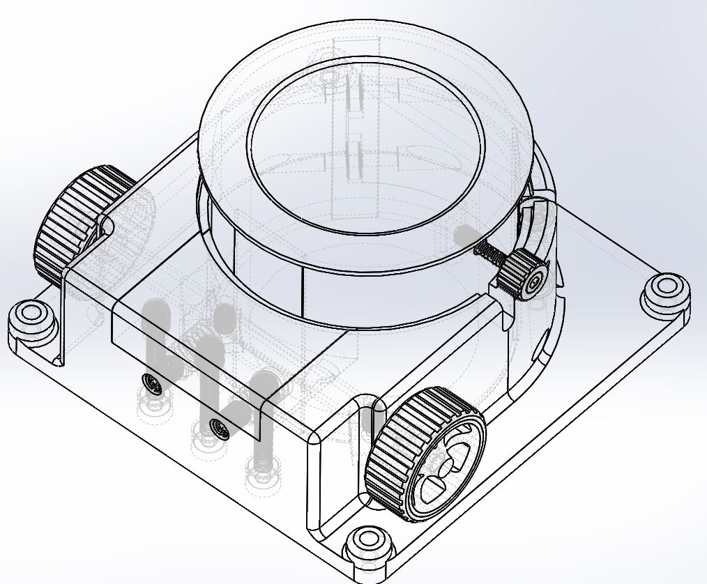
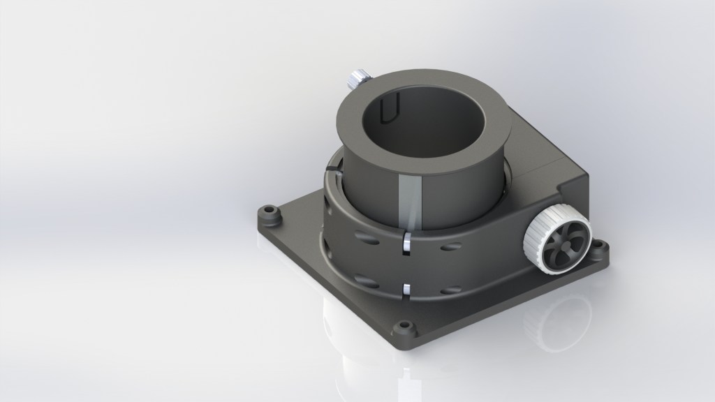
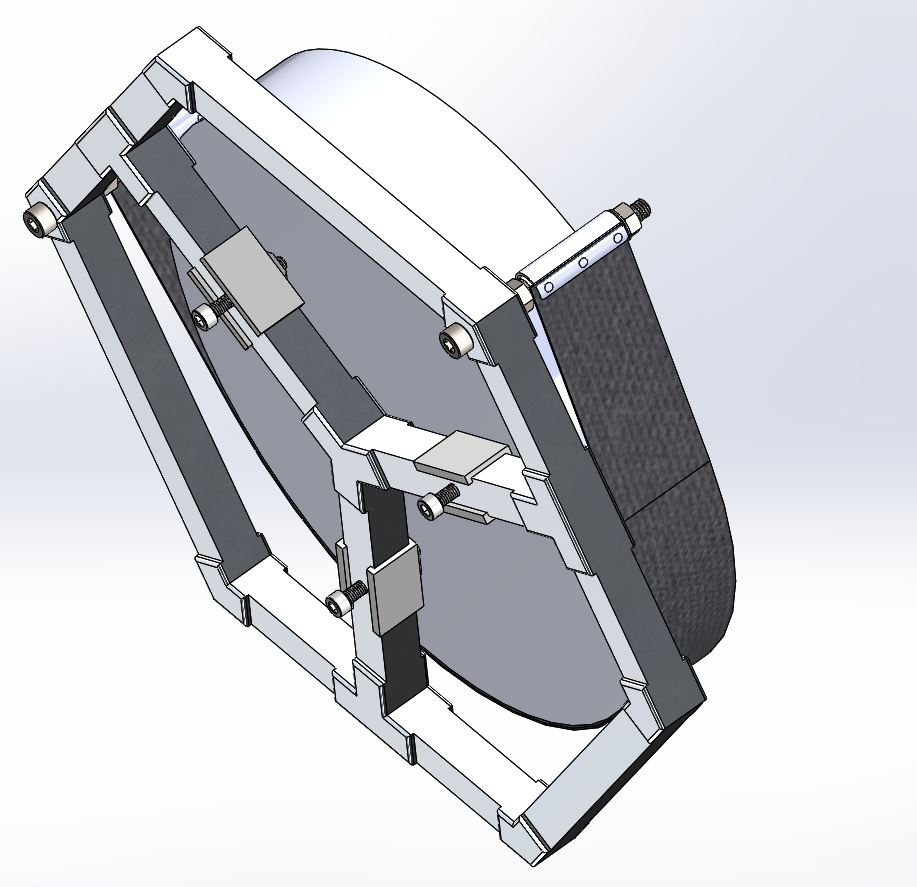
So after a few hours at the CAD coal-face (I use solidworks 2017) I came up with what is a pretty standard design but with a few tweaks to make it suitable for 3D printing.

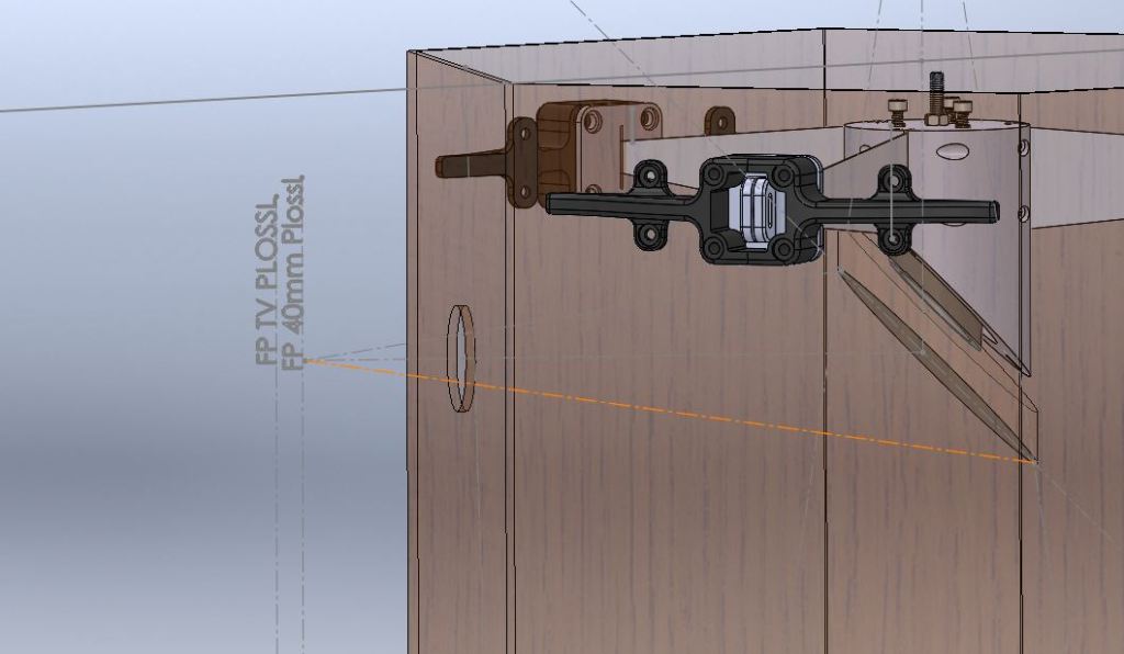
  1. The steel pinion on the focuser wheel and the rear 8mm bearings run against 1mm thick Aluminium plates that are bonded to Flat recessed areas on the drawtube. There are 2 reasons for this namely so I don’t have to post machine flats on the drawtube and also because the compression forces of the steel pinion and bearings permanently compressed against the plastic PLA would eventually indent it as it simply hasn’t got the surface hardness to survive the compression.
  2. Wall section is far thicker than you’d find on an Aluminium machined focuser for obvious reasons or strength and more importantly stiffness. This applies to both the drawtube and the base-plate.
  3. I’ve completed the circle “at the rear” if you like by adding a quadrant section that is bolted through to the main base-plate and THROUGH the 8mm bearings. Many Crayfords are open at the rear, but stiffness here is so important.
  4. The Draw tube nests FULLY down into the chassis so the top edge of the 2in eyepiece or adaptor is as far in as physically possible.

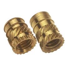
The rest is pretty much standard. Belt and braces. Most of the fixings are secured with “Heatserts” melted into the plastic printed holes with a soldering iron. They are super handy and super strong.

FEA

Some hand calculations and FEA to backup the calcs were done. The drawtube was loaded up with a force of 200N applied by the pinion (20Kg equivalent) to look at the deflection of the drawtube. It was around 0.15mm for printed PLA which is more than acceptable.

A basic free body diagram for the loads, static forces, sum of moments etc was done for the system assuming the worst case scenario: the drawtube fully extended with a 1.5Kg load at the end. This allowed me to decide upon a force to apply via the FEA to the drawtube.

Fully racked in the Focuser stands only 38mm High.

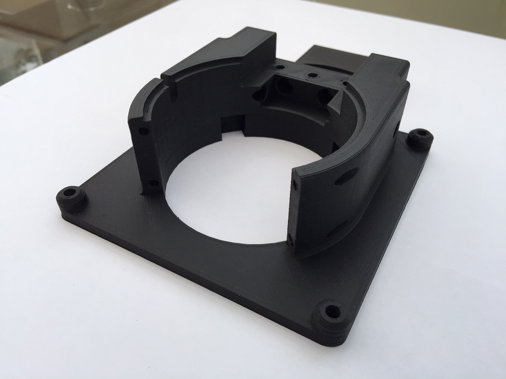
So to the prints……well these are the results of the first and largest part of the printing; namely the base plate The details of the printing deserve their own post. I use an Anet A8 which is by all accounts a budget home built printer but non-the-less produces excellent prints when well calibrated and set up.

The filament I am using is Matte black PLA
https://shop.3dfilaprint.com/filaprint-pla-matte-black-175mm-1kg-3d-printing-filament-15096-p.asp

This particular stuff is excellent, and extremely rigid produces neat prints.

NOW FOR A BIG DISCLAIMER!!!!!!!!!!! The FEA and calculations I have done are assuming that of a fully 100% filled part. However, I know I’m not lifting huge payloads of photographic equipment as this one will initially be used on my 12in F3.3 Dobsonian as a visual scope, MAYBE a small imager if I get it on an equatorial pier. My heaviest eyepiece combo will be a 24mm TV Panoptic+Coma corrector weighing about 350g. SO…….I printed at 20% fill with a 1.6mm wall thickness. Reducing the fully filled part from 160g to approx 90g. The strength will be lower yes, but not by much. It’s very surprising how strong 20% fill prints actually are. I use a fill called “Gyroid” for those initiated in 3D printing.

So here she is. The main chassis. I love plastic….Layer height was 0.2mm and they’ve come out very neat indeed. Within tolerance…..PLEASE…!!!!

Th build will resume shortly once the postman delivers the 5mm steel pinion shaft and some 8mm bearings…..I wait by the window with a nervous kind of energy.

To be continued………..

Not Quite First Light

Why is this such a scary moment? I’ve taken a newly silvered or new mirror out of it’s lint free cotton packaging and tissue paper a dozen times yet it still scares the c%^p out of me.

Looking into it’s freshly illuminised surface with not a microscopic blemish in sight is like looking into another bizarrely warped dimension. Knowing that it’s virgin surface will soon be covered in bug poo, dust, pollen and the mouth froth of an overexcited observer is heart-wrenching (for a few moments only).

At 12in diameter this 7.5kg F3.3 1/8wv P-V mirror was no mean feat when it was made 35 years ago so I approach with no small amount of trepidation!!

With the 75mm secondary installed EXACTLY as per the CAD but with temporary 3D printed spider vanes and a quick and dirty 3D printed focuser draw-tube (admittedly turned down a bit on my lathe for a bit better precision) the top end was approximately aligned with an old toy I purchased from Laser Max years ago…..

This 5mw laser with reticule does a nice quick job of approximately helping centring the secondary. A point to note is this setup INCLUDES the 5.6mm offset away and down from the eyepiece to centre the FOV. Another small point (literally); there’s only a small 7.5mm hole drilled in the side of the OTA art this point because if the position is not correct I can still drill the main draw-tube hole above or below the “test point”. That is however enough light for a star test.

So this is it. First light or more appropriately “First focus”. I don’t like calling this first light as all i’m trying to do here is get to the exact focal plane and make sure my CAD is all correct. The mount i’m using for the OTA is called the Camping seat non- equatorial tilter. It’s capable of not tracking anything and only pointing in one direction. It needs some work. Never the less I did manage to find a star!!!! and shove my phone camera up to the eyepiece.

So after a quick star test with a few different eyepieces I got the barrel stop position marked on my “focuser”. As it turns out I was only a few mm off the CAD meaning the stated F.L. of the mirror was very close to the actual. I’m about 60-70mm off the tube sides which is ample for use with a low profile Crayford and having enough back-focus for a coma corrector.

So that’s it. Drama over. It all gets stripped down now ready for it’s real components being installed, OTA blacked out inside. I can finalise the CAD now knowing where everything is exactly.

It’s amazing to think that those were the first photons of light from a star ever to be bounced off it’s surface in over 35 years as this mirror was actually made for a military laser firing test chamber on an alignment bed. It was never intended for use in a telescope. It of course has a paraboloidal figure. (it so happens, fortunately for me, that it’s original intended purpose needed to have a parabolic mirror).

Another way of looking at it is when this mirror was being ground and figured, the light leaving the Star Arcturus then (alpha bootis) has just arrived now so maybe i’ll catch some of that. The mirrors own birth light.

Gettin’ Jiggy Wit it.

3 Years ago if you’d ask me what I was going to do with my 3D printer I would have said, “I haven’t got a clue, they just look really cool”. I think the first human to invent the wheel wondered the same thing…..

f200bff684d27b73359d0e95dcc49e47

It’s difficult to understate how it’s changing lives and the way design is approached. But a word of caution. Printers are evil, the devils instruments. They are blasphemy. When I design for plastics I go to great care concerning draft for tooling, will it come out the mould correctly…. Are wall thicknesses correct, will I get sink, bloom etc…etc.. the list of plastic moulding pitfalls is ENDLESS!!  Where are the feed gates. OMG undercut, the CAD is wrong it’s gone to tooling…this mistake will cost $$$ to fix. Well all that design consideration has basically evaporated; all those hard learned rules can be thrown out the window. I tell you now, 3D printers are the bad boyfriend you never want your daughter to meet.

Unfortunately I’ve succumbed, turned to the dark side of printing. If you’ve not already realised it, you can now create geometries and impossibilities only previously conceived in the mind of an insomniac. Features within hidden cavities, honeycombed structure whose intricate innards opens up new worlds of hitherto unseen weight to strength ratios. It really is miraculous what you can do with a 3D printer.

Gushing ramble over, let’s get down to business with some very simple prints. If there’s one thing offered up by 3D printing it’s cheap, fast reliable jigs for  making and setting up the scope. I want the mirror cell bolts accurately drilled to the OTA on every facet identically; no problem, a small drill guide.

IMG_1919

Need to set your secondary centrally in the cell. This Jig, you just snip away after, makes it a cinch. (I do my secondary offsets from the secondary upper cage/vanes for the astute here! For an F3.3 12in scope that’s 5.6mm away and down.). The tabs UNDERNEATH the edge lip of the lower secondary cell, made transparent here, allow the mirror to stand 1.5mm off the surface of the edge whilst applying silicon. Th old method was a matchstick.


Or what about a secondary cell slider to work out where the secondary needs to be on the OTA. Not having an exact F.L. and needing to introduce a coma corrector has complicated matters. Don’t get too excited about the radioactive puke colour spider vanes. Both those and the side vertical sliders are temporary!! Only a small hole will be drilled out the side of the OTA for a quick star test with the coma corrector inline. The final vanes are 0.5mm Aluminium acid etch primed and coated BLK3.0


Another word of caution. I’ll do a separate blog on printer techniques and materials but never get too carried away with what you can create strength-wise. At the end of the day, it’s still a bit of plastic. There’s a time and a place so I wouldn’t go printing your equatorial drive shaft any time soon (some smart ass will print their equatorial drive shaft next week and put a 25in reflector on the end of it).

Well anyway the point is, a paradigm shift is required when thinking about how to use a 3D printer. That’s not the advertisers hyperbolic usage of the word paradigm by the way, I really do mean it in it’s truest sense and I can’t stress that more.

A very exiting time indeed, even if we are stuck in our houses.


Measure thrice cut once.

I’ll never forget Jupiter first light through my 4.5in homemade reflector slapped together with a hand drill, some MDF and a tub of glue. I was 18 years old, impatient, careless, hasty and completed all projects in less than 8 hours. or then not at all.

2

It’s a bit different nowadays. Mirrors wait 15 years in a box for the perfect OTA to install them into. Nothing short of a stroke of genius at the cutting edge of ATM deign propelling us to stardom in the ranks of all 946 of us. Meanwhile the stars have risen and set 5472 times just waiting to have their photons hit up by the perfect telescope. These particular photons should feel special! After rescuing a 12IN F3.3 parabolic ex-military laser firing test mirror from an industrial waste pile and getting it re-coated by the same company that made it 40 years prior with some Hilux 97% reflective coatings, that mirror should feel loved.

So a bit of care in the design department is warranted. I CAD everything up these days before going near a tool. The only thing I would say is that i’m not using the homemade crayford focuser in the CAD. And those Alt. bearings are being replaced with an experiment in untried bearing technology….ooooh a bit of suspense.

12inf3.3 1A12inf3.3 1B12inf3.3 1C

And the actual 3D printed Spider tensioners (I 3D rpint everything these days including my son and wife’s Xmas presents) and welded mirror cell ready to go into the OTA:

ATM Hiatus OVER! Discovering new joys in lock-down.

I’m so sorry folks. It’s been too long I’ve been away, multiple telescope projects lying dead or dormant collecting cobwebs, woodlouse and mouse poo in the darkest dingiest depths of my Alladin’s cave I call a garage but is actually a workshop/junk storage yard. Moving around it is like playing tiwster but with lots of sharp and heavy objects ready to smack you on the head the minute you are not looking.

To cut a long story short I dug out some half finished scope stuff, namely my 12in F3.3 OTA. Well it will be an OTA soon!! Right now it looks like a giant plywood Toblerone 6 pack that had it’s innards scooped out by a model aircraft enthusiast.

Here she is. I think it’s a she. Open to suggestion. You can look at her underside for confirmation.

I’m slopping on the PVA solution to seal the insides of the scope. No finesse here, sloppy slop slopping, the more the merrier. PVA is your friend. Short of drinking it to alleviate the stresses of being stuck in the house with your own family 24/7 (who I love very much but in lesser doses) it’s a marvellous substance for bonding, sealing, priming, waterproofing. We’re talking wood here. Don’t go putting any on your toast. It tastes funny. Sort of sweet and vinegar at the same time.

Anyway an esteemed ATM’r who we all know, Guy Brandenburg, advised that I texture the insides of the scope as i’m applying the PVA; that reduces further any stray light once the black paint is applied to the inside walls and increases absorption etc…What we’re wanting to do is ABSOLUTELY maximise contrast in a rich field telescope like this. Blacker than a black hole. I want this OTA sucking in the very matter i’m surrounded by including the snorkel I use when doing planetary observation to direct my warm breath over my shoulder instead of into the optical path.. I exaggerate. A small point to note, I evened out the sawdust more than is in the picture by “stippling” the brush.

I’ve just given it a quick beeswax to protect the OTA wood because i’m working on it presently and this will prevent any staining. It will be properly finished after the dry fit of the mirror cell, secondary, focuser etc.
Beeswax or oil seems to be the way to go though. There’s nothing like the natural feel of wood, the smell, the grain pop out like an excited child dying to show off their latest trick.

And in case you’re wondering how I create a singularity within my garage, i’m using this bad boy. This black is so black, that when is sat down and had conversation with a black hole, the black hole said “damn you’re your black, in fact I can’t even see you, who are you?” The thing replied “I’m BLK3.0 and i’m gonna suck your ass into another universe”. Some clever guy called Stuart Semple invented it and licensed it to everyone except some dude called Kapoor that licensed a color that nobody else could use. Or some shit like that. I’m not making this up, it actually happened.